On many occasions, it is very handy or even essential to have relatively simple devices to detect or quantify ionizing radiation. Three important applications for such devices are:
To determine the amount of radioactivity in a syringe, so that one can adjust and/or verify how much activity is going to be administered to the patient.
To determine the amount of radioactivity in a sample (usually blood samples) taken from the patient. The problem is the same as the former one, but the amount of radioactivity in a small sample is typically orders of magnitude less than the injected dose.
To detect contaminations with radioactivity, e.g. due to accidents with a syringe or a phantom.
To use a PET or gamma camera for these tasks would obviously be overkill (no imaging required), impractical (they are large and expensive machines) and inefficient (for these tasks, relatively simple systems with better sensitivity can be designed). Special detectors have been designed for each of these tasks:
the well counter, for measuring small amounts of activity in small volumes,
the radionuclide calibrator for measuring high amounts of activity in small volumes,
the survey meter for finding radioactivity in places where there should be none.
Well counter

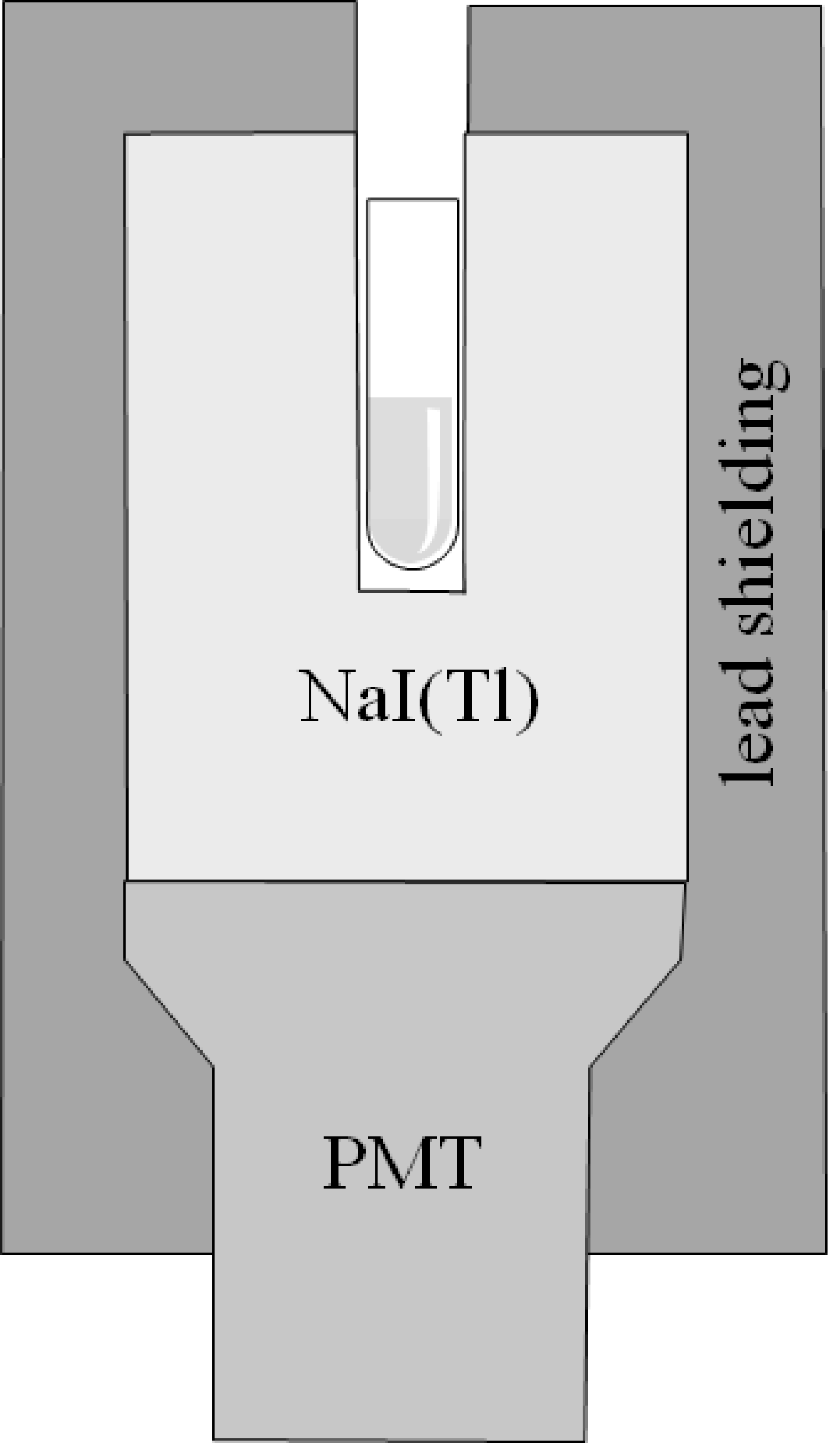
Figure 1:Diagram of a well counter, showing a test tube inside the well.
The well counter consists of a scintillator crystal, typically NaI(Tl), a PMT, lead shielding and electronics to control the PMT and the user interface. The crystal has a cavity (the well), in which a test tube (or any other small object) with a radioactive substance can be put. As illustrated in Figure 1, the radioactive substance is almost completely surrounded by the scintillator crystal. This gives the well counter an extremely high sensitivity, enabling it to detect minute quantities of radioactivity. The well counter detects individual photons, and similar to a gamma camera, it can estimate the energy of the detected photon with an energy resolution of about 10%.
The crystal is usually several centimeters thick to further improve the detection efficiency. The efficiency decreases (non-linearly) with increasing energy, because photons with higher energy have a higher probability of traveling through the crystal without interaction. The effect of the crystal thickness can be taken into account by calibrating the well counter, which is done by the vendor.

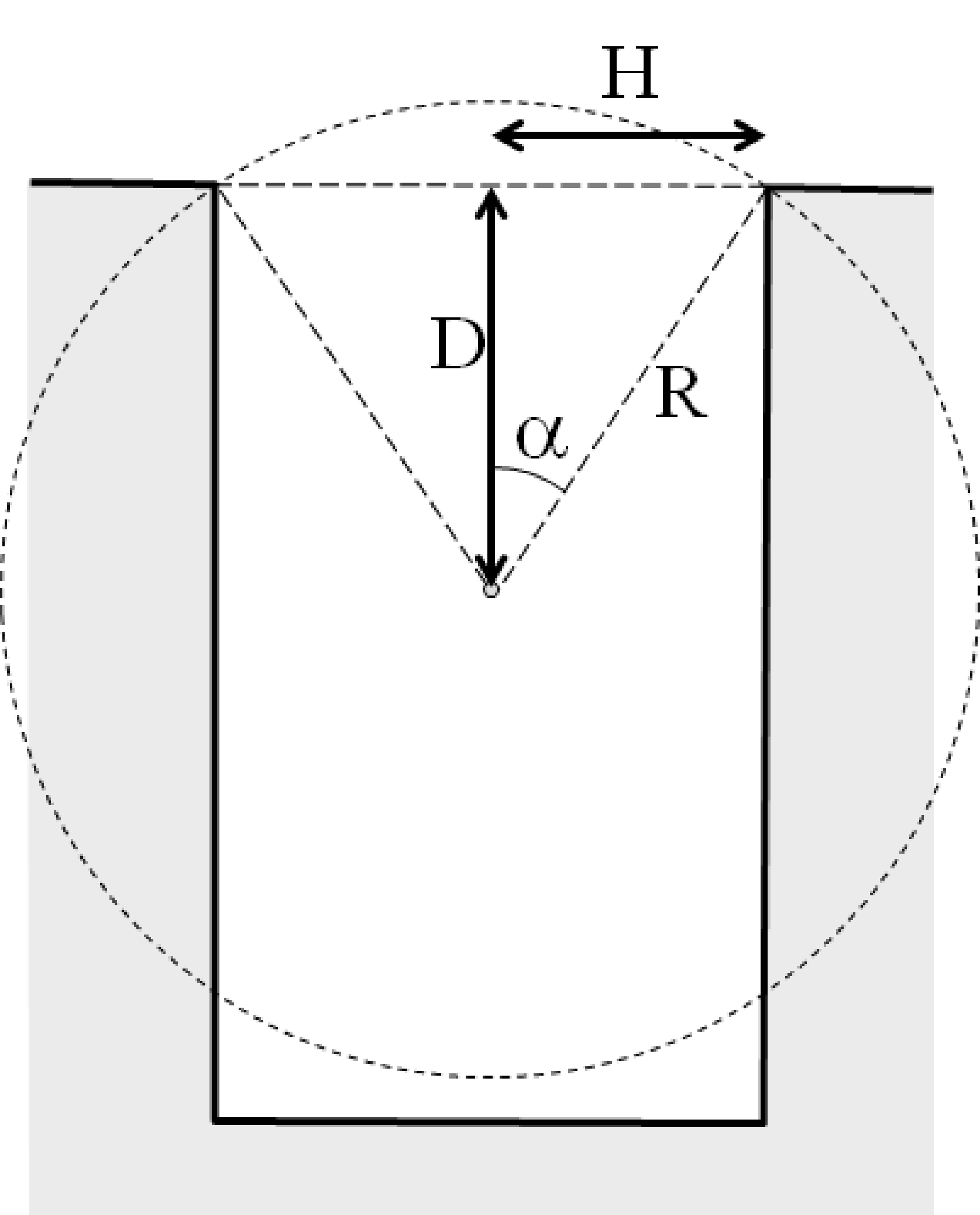
Figure 2:Left: diagram of a well counter, showing a test tube inside the well. Right: the geometrical sensitivity of the well counter to activity inside the tube, as a function of the depth inside the crystal (H = 2 cm).
One problem of the well counter is that its sensitivity varies with the position of the source inside the crystal: the deeper a point source is positioned inside the crystal, the smaller the chance that its photons will escape through the entrance of the cavity. A simple approximate calculation illustrates the effect. Suppose that the radius of the cylindrical cavity is and that a point source is positioned centrally in the hole at a depth . As illustrated in Figure 2, we have to compute the solid angle of the entrance, as seen from the point source, to obtain the chance that a photon escapes. A similar computation was done near equation (8), but this time, we cannot ignore the curvature of the sphere surface, because the entrance hole is fairly large:
where the value of in the integral goes from to . A particular value of defines a circular line on the sphere, and a small increment turns the line into a small strip with thickness .
Substituting one obtains:
And the chance that the photon will be detected equals
We find that for , the sensitivity is 0.5, which makes sense, because all photons going up will escape and all photons going down will hit the crystal. For going to ∞, the sensitivity goes to unity. Note that the equation also holds for negative , which means putting above the crystal. That makes the sensitivity smaller than 0.5, and for , the sensitivity becomes zero. A plot of the sensitivity as a function of the depth is also shown in Figure 2, for = 2 cm, i.e. a cylinder diameter of 4 cm. This figure clearly shows that the sensitivity variations are not negligible. One should obviously put objects as deep as possible inside the crystal. Suppose we have two identical test tubes, both with exactly the same amount of activity, but dissolved in different amounts of water. If we measure the test tubes one after the other with a well counter, putting each tube in exactly the same position, the tube with less water will produce more counts!
Expression (4) is approximate in an optimistic way, because it ignores (amongst other effects) the possibility of a photon traveling through the crystal without any interaction. Although the well counter is well shielded, it not impossible that there would be other sources of radioactivity in the vicinity of the device, which could contribute a bit of radiation during the measurement. Even a very small amount of background radiation could influence the measurement, in particular if samples with very low activity are being measured. For that reason, the well counter can do a background measurement (simply a measurement without a source in the detector), and subtract the recorded value from subsequent measurements. Of course, if there would be a significant background contribution, it would usually be much better to remove or shield it than to leave it there and correct for it.
Radionuclide calibrator
Because the radionuclide calibrator is a gas filled detector, a small introduction to gas filled detectors is given first.
Gas filled detectors
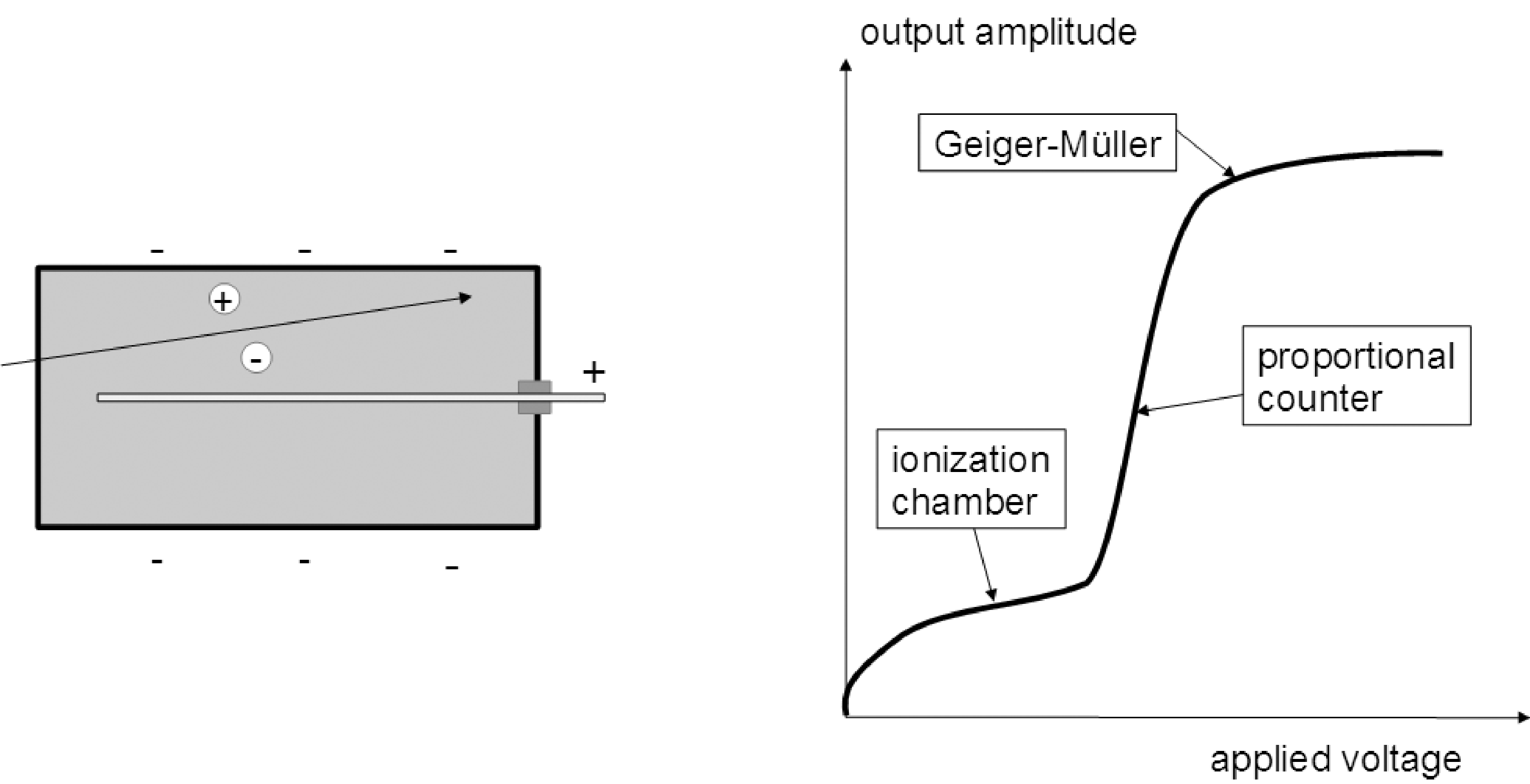
A gas filled detector consists of an anode and a cathode with a gas between them. When a photon or particle travels through the gas, it will ionize some of the atoms in the gas. If there would be no voltage difference between the anode and the cathode, the electrons and ions would recombine. But with a non-zero voltage, the electrons and positive ions travel to the anode and cathode respectively, creating a small current. If enough atoms are ionized, that current can be measured. A cartoon drawing is shown in Figure 3.
If the voltage between the cathode and the anode is low, the electrons and ions travel slowly, and have still time to recombine into neutral atoms. As a result, only a fraction of them will reach the electrodes and contribute to a current between anode and cathode. That fraction increases with increasing voltage, until it becomes unity (i.e. all ionizations contribute to the current). Further increases in the voltage have little effect on the measured current. This first plateau in the amplitude vs voltage curve (Figure 3) is the region where ionization chambers are typically operated. In this mode, the output is proportional to the total number of ionizations, which in turn is proportional to the energy of the particles. A single particle does not produce a measurable current, but if many particles travel through the ionization chamber, they create a measurable current which is proportional to the total energy deposited in the gas per unit of time.

Figure 3:The gas detector. Left: the detector consists of a box containing a gas. In this drawing, the anode is a central wire, the cathode is the surrounding box. A photon or particle traveling through the gas produces ionizations, which produce a current between anode and cathode. Right: the current created by a particle depends on the applied voltage.
With increasing voltage, the speed of the electrons pulled towards the anode increases. If that speed is sufficiently high, the electrons have enough energy to ionize the gas atoms too. This avalanche effect increases the number of ionizations, resulting in a magnification of the measured current. This is the region where proportional counters are operated. As schematically illustrated in Figure 3, the amplification increases with the voltage. In this mode, a single particle can create a measurable current, and that current is proportional to the energy deposited by that particle in the gas.
With a still higher voltage, the avalanche effect is so high that a maximum effect is reached, and the output becomes independent of the energy deposited by the traversing particle. The reason is that the electrons hit the anode with such a high energy that UV photons are emitted. Some of those UV photons travel through the gas and liberate even more electrons. In this mode, the gas detector can be used as a Geiger-Muller counter. [1]
The Geiger-Muller counter detects individual particles, but its output is independent of the energy deposited by the particle.
Radionuclide calibrator
A radionuclide calibrator looks similar to a well counter, it also has a small cylindrical hole surrounded by the detector. But instead of a crystal with PMT, an ionisation chamber is used.
The output of the detector is proportional to the total number of ionized gas atoms, which in turn is proportional to the energy deposited in the gas, and therefore also proportional to the activity put in the detector gap. The detector measures the contribution of many photons simultaneously, and therefore it obtains no information about the energy of individual photons. This lack of energy discrimination is a drawback, but the capability of dealing with many simultaneous incident photons (or other particles) makes this detector useful for the measurement of high activities (which would saturate photon counting devices, see section Dead time correction).
Ionisation chambers often use air, but for radionuclide calibrators, typically pressurised Argon is used. The high pressure in the chamber reduces the sensitivity to the atmospheric pressure. In addition, the high pressure (more atoms) and the higher attenuation of Ar improve the sensitivity of the detector. Radionuclide calibrators designed for higher activities (up to ± 20 Ci or ± 750 GBq) use typically a pressure of around 5 bar. These radionuclide calibrators are more likely to be found at PET sites, where higher activities can be used because of the short half lifes of most PET isotopes. For quantifying lower activities (up to ± 5 Ci or ± 200 GBq), radionuclide calibrators with a higher pressure (± 12 bar) are used, because a higher pressure improves the stability for low activity counting.
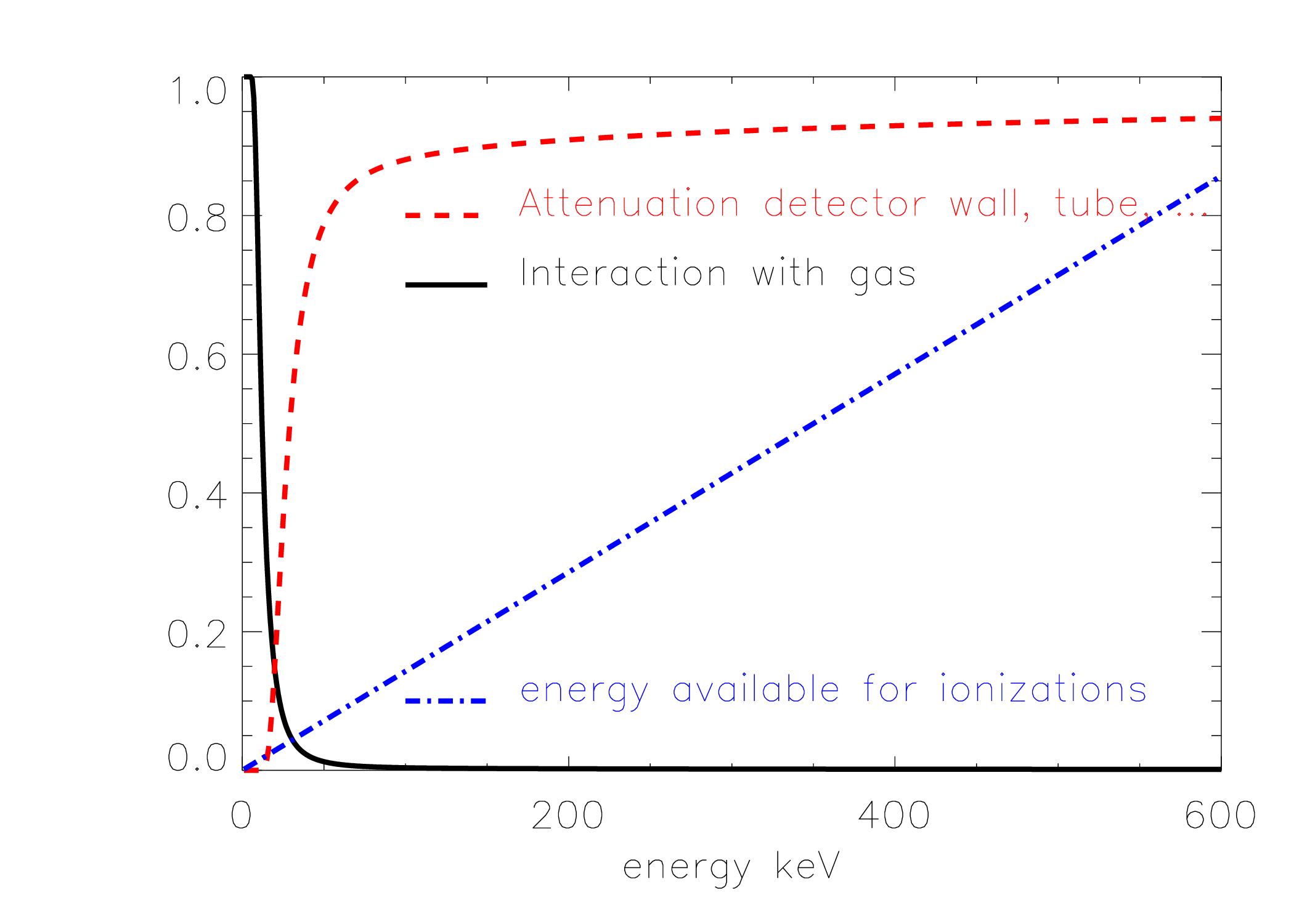
Since the geometry of the radionuclide calibrator is similar to that of the well counter, it suffers from the same position dependent response illustrated in Figure 2. But in contrast to the well counter, the response of the radionuclide calibrator is also heavily dependent upon the energy of the photons emitted by the isotope. The photons have to reach the gas, and to do so, they must travel through the water in the test tube, through the wall of the test tube and through the wall of the radionuclide calibrator. Then, they have to interact with the gas to produce ionisations. The probability of interactions (attenuation) decreases with increasing energy. Finally, in every interaction, a few tens of eV are transferred, so the higher the energy of the photon, the more ionisations that same photon could produce. These three effects are illustrated in Figure 4. The figure also shows their product, which has a sharp local maximum at low energies, and increases with increasing energy. This is only a rough approximation, the actual curve for a particular radionuclide calibrator depends on many things and it is safer (and much easier) to measure it than to compute it. Knowing the emissions of a particular isotope, and the sensitivity of the radionuclide calibrator for each of those emissions, one can deduce the activity of the isotope from the radionuclide calibrator measurement. A well calibrated radionuclide calibrator will do this automatically for you, you only have to tell it which isotope you are measuring, typically by selecting it from a menu.
The high sensitivity at low energies can be problematic for isotopes such as 123I and 111In, which emit a fairly large amount of low energy photons (see Table 1). The problem is that these low energy photons are easily attenuated by a little bit of water or a small amount of glass, and therefore, the dosis calibrator would give very different responses when measuring the same activity in different test tubes. The reproducibility improves dramatically when these photons are eliminated by adding a bit of attenuating material, such as a “Cu-filter”. This filter is basically a copper recipient with a very thin wall (half a mm or less), which has very high attenuation for low energies, but only moderate attenuation for higher energies. This is illustrated in the right panel of Figure 4.
Table 1:Emissions of 123I and 111In.
Energy [keV] | Iodine-123 emissions | Energy | Indium-111 emissions |
159 | 83.5% | 172 | 90% |
247 | 94% | ||
27 | 71 % | 23 | 70% |
31 | 15 % | 26 | 14% |

Figure 4:Left: loss of photons due to attenuation in the test tube, detector wall etc., probability of interaction of the photons with the gas and the number of ionisations that could be produced with the energy of the photon (in arbitrary units), all as a function of the photon energy. Right: the combination of these three effects yields the sensitivity of the radionuclide calibrator as a function of the photon energy (solid line). The dashed line shows the sensitivity when the sample is surrounded by an additional Cu-filter of 0.2 mm thick.
Just like the well counter, the dosis calibrator can measure the background contribution and correct for it during measurements of radioactive sources.
Radionuclide calibrators are designed to be very accurate, but to fully exploit that accuracy, they should be used with care (e.g. using Cu-filters when needed, position the syringe correctly et), and their performance should be monitored with a rigorous quality control procedure.
An important quality control test is to verify the linearity of the radionuclide calibrator over the entire range of activities that is supported, from 1 MBq to about 400 GBq.
Survey meter
Survey meters are small hand held, battery powered devices, usually containing a gas detector, i.e. an unshielded ionization chamber, proportional counter or Geiger-Muller counter. Survey meters based on ionization chambers basically measure the energy deposited in a particular mass of air, i.e. the air Kerma, where “Kerma” stands for “kinetic energy released in media”. Air Kerma is the amount of energy per unit mass released in air, and has units of Gy. The output of such a dosimeter would then typically be expressed in microGy/hr or similar unit. Since the attenuation per gram air is similar to the attenuation per gram tissue, air Kerma provides a reasonable estimate of the absorbed dose in human tissues produced by the radiation, the conversion factor is about 1.1, so
Other types of survey meters use a Geiger-Muller counter. Often the device has a microphone and makes a clicking sound for every detected particle. The Geiger-Muller counter counts the incoming photons (or other particles), but it does not measure its energy.
Finally, still other survey meters contain a scintillation crystal with photomultiplier. These are also called “contamination monitors”, because they can be used to measure the spectrum of the activity, to find out which tracer has caused the contamination. This is important information: a contamination with a long lived tracer is obviously a more serious problem than with a short lived tracer.
Most survey meters can usually measure both photons and beta-particles (electrons and positrons). Remember that to measure contamination with beta-particles, the survey meter must be hold at small distance, because in contrast to x-rays or gamma rays, beta-particles have non-negigible attenuation in air.
Special tricks must actually be used to make sure that the avalanche dies out after a while, the avalanche must be quenched. A common approach is to use “quenching gases”, which happen to have the right features to avoid the excessive positive feedback that would maintain the ionization avalanche.